
 We all know that changing your building venue helps you get out of a case of “modelers block”. Well I can say it’s one hundred percent true. I’m a 1/72 scale builder of Pioneer and WWI aircraft with a special affinity for vacuform models. After completing my latest project, a Westland Pterodactyl flying wing (a future newsletter candidate) I felt really burnt out, just did not want to build anything!
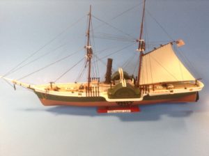
One night I was communing with my stash trying to get some inspiration and then I saw the Lindberg 1/124th scale model of the USS Harriet Lane, a Civil War side wheel steam ship. This is a very old kit, originally produced by Pyro Plastics of Union New Jersey back in the late 50’s. This model appealed to me as it was different from my normal builds yet it had complexity in the rigging of the sails and masts, and I dearly like rigging biplanes! So without further thought the Harriet Lane went from stash to bench.
I did a little research on the history of the Harriet Lane. First I found out that it was not 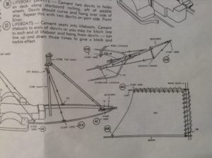 a USS, that is a United States Ship, but rather a USRC, a United States Revenue Cutter. It was used in the Civil War by the Union Navy until 1863 when it was captured by the Confederates at the battle of Virginia Point. The ship was then used by the Confederates as a blockade runner until recaptured by the Union forces about a year later. After capture the Harriet Lane was found unfit for service. It was renamed the USS Elliot Ritche and sold at Philadelphia in late 1865. The ship lasted until 1868 when it was abandoned at sea. Ok class, history lesson over, no quiz, onto the model.
Opening the box I was very surprised to find the hulls wrapped in tissue paper as were the masts. This was done to prevent damage to the parts, and something I had not seen in a long time, kind of shows the age of this kit.
First thing I read was the instructions and this was a real treat. Knowing little of ship terminology I was pleased to find that they used nautical terms. For example, you know those “L” shaped pieces that the anchors are attached to, they’re called a “cat head”.
We all know that the long horizontal mast at the very front of the ship is called the “bowsprit” but I bet you never knew that the little arm hanging down from it is called the “dolphin striker”, a very politically incorrect name in today’s animal friendly society!
 First thing was getting the two piece hull together along with the deck. The pieces went together perfectly, no flash at all. I had painted ( Tamiya paints used throughout) the deck XF-78 Wooden Deck Tan (what else would you use). The upper portion of the hull was painted XF-26 Deep Green, the lower portion XF-6 Copper, with the side railings XF-2 White. The decorative carvings on the bow and paddle wheel housing was highlighted with Rub-N-Buff Antique Gold. By the way I used Tamiya curved surface masking tape on the hull, it worked beautifully, many thanks to Marc Rocca for recommending the stuff!
Ok, the hull is done and onto the side wheel paddles and here’s where it starts to get interesting. Each paddle wheel has twenty five parts and they are “handed” meaning there’s a left and right. You really had to pay attention to the instructions to get it right. Here’s a sample of text from the instructions:
STEP 12 Take one paddle wheel side spoke unit with the blind side hole and one with the hole running through it. Cement paddle boards across the wheel spokes. Notch on paddles fit over rim of side units. Line your assembly up carefully. Make two of these units. Note that paddle boards must be on front edge of spokes to make a right and left unit. You know it took me over three hours to get these things right! But wait it gets better.
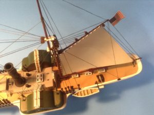
Once the paddle wheels and pilot house had been completed and attached to the hull it was time for the masts and boy did I get an education. Do you know that the masts and their individual parts have individual names? The front mast is called a “foremast” and the rear one a “main mast”. The bottom cross member of the “foremast” is called the “fore yard”, the middle cross member is called the “fore topsail yard” and the top cross member the “top gallant yard”. The top of the “foremast” is called the “fore top mast” (only one that made sense so far) and that they were connected together by a “cross tree”.
See those two horizontal arms coming off the “main mast” (that’s the rear mast) and supporting the “steadying sail”. The top one is called the “gaff” and the bottom the “boom”. And you know something? All these individual parts kind of look the same. You had to really read and comprehend the instructions before you started gluing. It was so easy to make a mistake.
I painted the mast assemblies XF-59 Desert Yellow and streaked them with XF-10 Brown to give a wood effect, with Micro Scale gloss for a final finish. This was not unlike the technique I use for wooden struts and propellers for my aircraft. The “cross trees” were painted XF-2 White. It took three late night modeling sessions to correctly layout and complete the masts.
After the masts were completed I had to build the “windlass”, that’s the thing that lifts 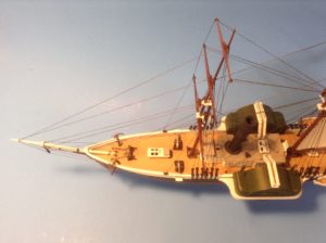 the anchors. I used the kit supplied anchor chain (real metal chain!) and followed the instructions carefully with no problems. By the way that cross piece on the anchor is called the “anchor stock” and that’s what holds the anchor to the “cats head”. If you’ve read the article you’ll know what the “cats head” is all about.
I then completed all the items for the deck. The pilot house was painted XF-2 White, with XF-53 Neutral Gray for the roof. The windows for the pilot house and main cabin skylights were finished with Testors clear plastic cement. The smokestack was painted XF-84 Dark Iron with some XF-1 Black streaked on for a little weathering. The steam whistle was picked out with XF-6 Copper. And I just couldn’t resist, the smokestack support wires are made from stretched sprue. The cannon barrels were painted XF-56 Metallic Gray with their carriages painted the same way as the masts. The life boats were done in XF-2 White with XF-10 Brown for internal structure.
With the model basically completed it was on to the rigging and this is where the instructions were invaluable. They showed you where to start and finish and worked in a logical manner so completed work did not interfere with work yet to be done. Also you had to be careful where you placed the “blocks” (that’s the pulleys the rope went through) on the masts. There were single and double “blocks” and their attachment angle was critical.
I won’t go much into the individual rigging projects but the rigging of the “steadying sail”, that’s the one in back is worth describing. The sail was one piece of injected plastic, not vacu-form, with holes molded in to support the rigging. These holes had to be cleaned with a #60 drill to ease passing of the thread. By the way the “steadying sail was painted with Insignia White out of a rattle can with a little brown pastel used for weathering.
You started with one long piece of kit supplied thread and secured it at the tail end of the “gaff” and then looped it thought the holes in the sail and around the “gaff”. You continued along the “gaff” until you hit the “main mast” and then continued down till you hit the bottom of the mast and secured it to the “fife rail”, a structure at the bottom of the mast. The lower trailing end of the “steadying sail” was secured to the “boom” with a small loop of thread. The “steadying sail” was centered by attaching thread from a “cleat” (that’s one of those anvil shaped things on the top of the railing) up across the end of the “gaff” and then down to another “cleat” on the opposite railing.
I should point out that I’m not very good with tying knots and maybe this might make a lot of ship modelers cringe in horror but I secured the ends of the thread with super glue and then cut the loose end. A little Micro Scale flat took the sheen off the glue.
And here’s your final history lesson. See the railings that run from one paddle wheel housing to the other? It was called the “bridge” and steering commands were issued from the center of the “bridge”. This is how the term “bridge” came into use.
All in all this was a very pleasant build that I thoroughly enjoyed. It really broke my “modelers block”. I’ve got to say something about the quality of the instructions. They were the original Pyro Plastics instructions from the late 50’s were immensely interesting. You had to learn new terms and really had to read and comprehend them to produce a good model. Further, this model was meant for a kid to build, with a little help from the parents. Models like this educated the builders and fostered family ties. It’s so sad that things like this are rapidly being lost in our turbulent times. Anyway, enough on the philosophy…thanks for reading….now get building something and complete it for a change! ~Mike Terre, September 2016